

how to draw sequense diagram using enterprise architect ppt
Custom Diagram Styles
Enterprise Architect provides a diagram drawing style that helps you lot to create new diagrams or cast existing diagrams every bit simple, colorful and direct illustrations of modeling and project direction concepts, similar to the style of drawings created in Visio or Powerpoint. Elements are rendered with a border color, fill color, no gradients and a simplified appearance. They can also be rendered in a range of different shapes.
This minimalist drawing style is much used past architects, business users, CEOs and many others every bit a preferred means of carrying advertising-hoc data concerning a business capability, architecture, system interaction or whatever of several other scenarios. In providing this capability, Enterprise Architect dramatically increases the reach and audience for its range of diagrams. Coupled with WebEA and Prolaborate, the facility offers end users instant access to bonny and familiar diagrams that avoid the formal, technical appearance and complexity of UML and technology diagrams.
The custom cartoon style can be applied to any UML diagram, then that a user can still use the correct modeling element types (and tin can toggle back to the formal rendering of these elements) but they tin give them a completely novel rendering way and appearance.
Custom Diagram Style is available in the Corporate, Unified and Ultimate Editions of Enterprise Architect from release 15.0 onwards.
Access
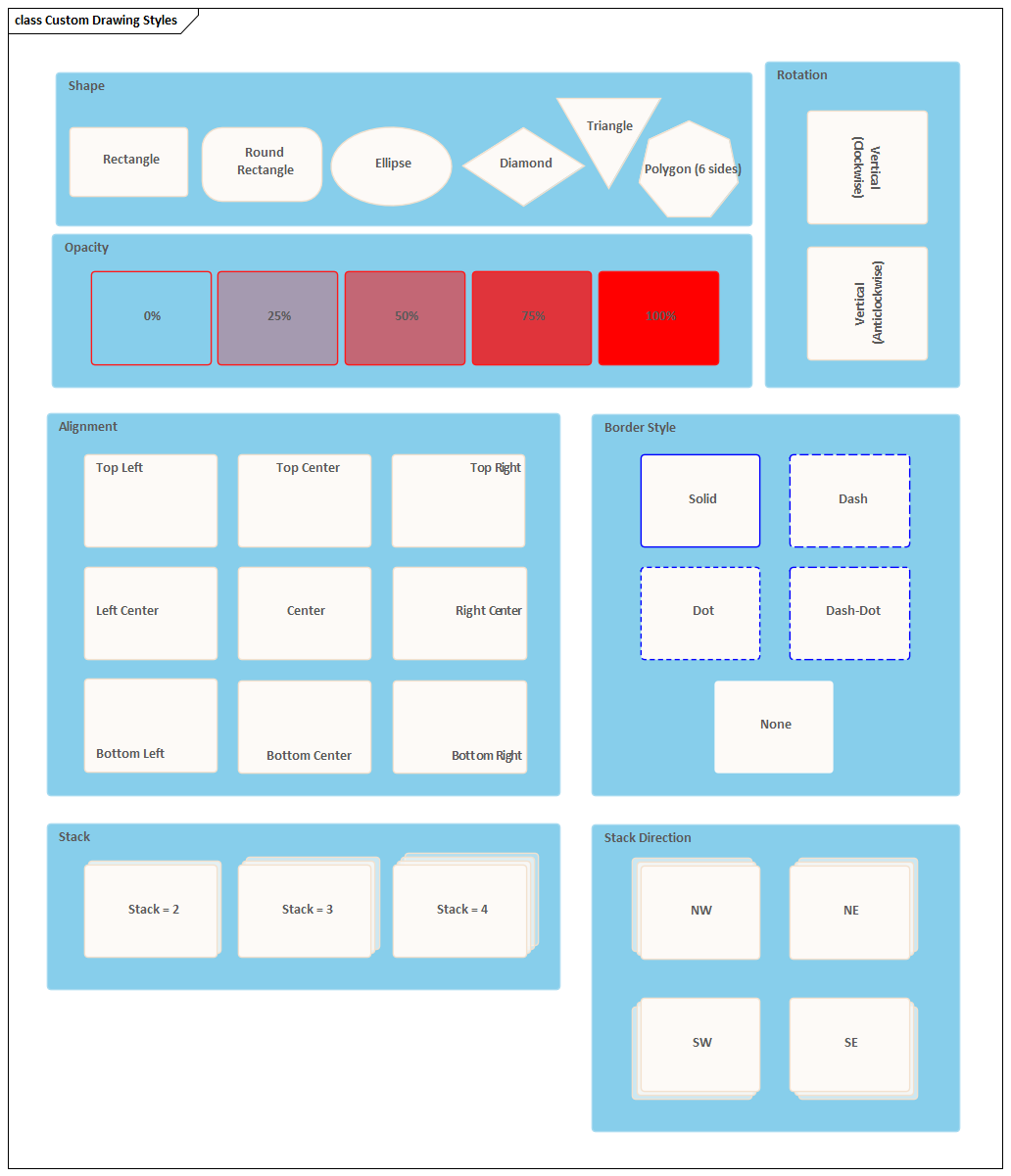
| Working from a template or Pattern | Display the Model Wizard (right-click on a Parcel and select the 'Add a Model using Wizard' option) and in the 'Model Patterns' tab click on the 'Perspective' drop-downwardly arrow and select 'Analysis > Custom Diagram Style'. Select one of the three templates or six examples, and work on those to develop your own diagrams. Annotation that these templates are intended to illustrate the feature rather than provide a framework for modeling - customizing is, after all, doing things your way! We recommend generating a model from the Custom Drawing Styles template (the diagram is shown in the Examples of Style Rendering section of this topic) and experimenting with the shapes and features to help you develop your own rendering of elements. |
| Utilise the fashion to an existing diagram | Open the Properties window () and the required diagram, and click on the diagram background. On the 'Diagram' tab of the Properties window, expand the 'Advent' segment and select the 'Custom Style' checkbox. Alternatively, double-click on the diagram background to display the 'Properties' dialog, select the 'Elements' tab and select the 'Custom Describe' checkbox. All elements on the diagram are rendered as white rectangles with the element name and stereotype in the eye. However, structural elements (such equally a Ports) are not rendered differently in Custom Style. 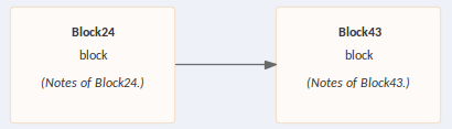 If the element has Notes, these are also displayed in parentheses. No other element properties or characteristics are shown. Connectors on the diagram are simplified to a solid line and basic arrowhead, except for stereotyped connectors which are as well not rendered differently in Custom Style. You lot now click on each element in turn and click on the |
| Enable the mode for an individual element | If the 'Custom Manner' choice on the diagram is not selected, yous tin can apply the style to an individual element on the diagram. Right-click on the element and select the 'Appearance | Enable Custom Draw Style' context carte du jour selection. The element - alone on the diagram - is shown as a white rectangle equally shown in the earlier case. When either of the 'Enable Custom Draw Manner' or diagram 'Custom Style' options are selected, when you click on the element and on the 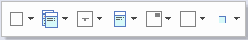 |
 icon to ascertain the rendering as described in the rest of this topic. You can every bit apply each feature to a pick of multiple elements.
Examples of Style Rendering
In the descriptions provided in this topic, refer to this diagram as an illustration of the options and their furnishings.
Apply Styles
| Set the Shape | On the Format toolbar click on the
Encounter the 'Shape' panel of the case diagram. The 'None' option here turns custom styles off for the chemical element and returns it to 'normal' model notation rendering. Regardless of its visible shape, each element has a rectangular performance boundary and the positioning options described in this table work within that rectangle. You might detect, therefore, that some of the position options on non-rectangular shapes can place the element text and icons outside the visible shape. Notation that the icon in the toolbar updates to reflect the current shape of the element. | |
| Set the Opacity of the Element Make full | You tin can set the element shape to be transparent (then that the diagram groundwork and any overlapped elements show through) or various degrees of opacity that overshadow the overlapped elements. If yous set 100% opacity, the element fill up is solid and totally hides the background and any overlapped elements. To set the opacity, on the Format toolbar click on the
Run into the 'Opacity' console of the example diagram. Annotation that the element boundary, text and icon (if gear up) are not afflicted when setting the Opacity. | Organization Boundary Properties |
| Set the Text Position | On the chemical element, brandish of the name, stereotype and notes defaults to the centre of the chemical element. You lot can reposition the text to 8 other points in the chemical element shape, or place the text in a custom position. To position the text, on the Format toolbar click on the
If yous select the 'Custom' option, the element text is displayed as a characterization just beneath the element, and you tin can elevate information technology to whatever position inside or exterior the chemical element y'all prefer. You tin also utilise any of the standard label formatting facilities. See the 'Alignment' panel of the case diagram. Note that the icon in the toolbar reflects the current position of the text in the selected element. | Manage Object Labels |
| Ready the Text Orientation | The text in the element defaults to horizontal, reading left to correct. If you adopt, you tin set the element proper name to a vertical orientation with characters in the same airplane, reading either top to bottom or lesser to top. Stereotype and Notes text are hidden in these vertical settings. To set the orientation, on the Format toolbar click on the
See the 'Rotation' panel of the instance diagram. Note that the icon in the toolbar reflects the current orientation of the name of the selected element. | |
| Add an Icon to an Element | While the diagram has Custom Style enabled, you tin add icons to either the existing elements or to new elements generated as part of the process. The default position of the icon is in the height right corner of the element purlieus, but you tin move the icon to other points. To set the icon on an element in the diagram, select an Prototype Asset in the Browser window and elevate it onto the diagram, either onto the existing element or into a infinite in which to create a new chemical element. A brusk menu displays:
Afterwards adding the icon, click on the chemical element and on the
Note that the toolbar icon reflects the current position of the icon in the selected chemical element. Any size of image can be set into the Image Asset when information technology is used every bit an icon, but you can command its display size in the element. Click again on the
| Paradigm Assets |
| Use Border Style | To change the border line fashion, on the Format toolbar click on the
See the 'Border Manner' panel of the example diagram. | |
| Utilise Stacked Paradigm | On the diagram or element with Custom Way enabled, you can make an element represent several iterations of its object by adding a ready of between 1 and 4 'stacked' element edges off one of the corners of the element. To add 'stacking', click on the Click on the
Run across the 'Stack' and 'Stack Management' panels of the example diagram. Annotation that the icon in the toolbar also reflects the management of stacking in the selected element. | |
| Set the Font, Edge Width and Colors | These are standard options on the Diagram and Element floating toolbars, and use to the Custom Styles also as to normally rendered elements. Click on the element and on the
| Create Custom Colors |
 icon at the correct-hand end of the row of icons. In the driblet-downwards menu, click on the appropriate shape option to return the element as a:
 icon and select from:
 icon and select from these options:
 icon and select from these options:
 icon and select 'Stacks' and the number of edges to add together.
 icon again (find that it now represents the number of 'stacks' yous ready) and select 'Management' and one of these options:
 icon to the correct of the chemical element to display the Element toolbar, then:
 icon; the 'Font' dialog displays, on which yous can set the font type, style, size, color, effects and script type from the lists in each field
 icons to fix the colour of the text, element fill and/or chemical element edge respectively; select the appropriate color from the color palette in each instance or, if necessary, click on the
 Subordinate Text
In Custom Diagram Style, if the element name does non provide a sufficiently specific visual reference, you can use the 'Description' Tagged Value to display a secondary text string on the element. Apply these unproblematic steps:
- Click on the chemical element and, if necessary, printing to brandish the Properties window for the element.
- Click on the 'Tags' tab in the Backdrop window, and click on the
 icon in the toolbar to create a new Tagged Value.
 - In the 'Tagged Value' dialog, in the 'Tag' field type Description, and in the 'Value' field blazon <memo>. Click on the .
- On the 'Tags' tab, click on the
 icon at the right-manus finish of the 'Description' field, and in the 'Tagged Value Note' dialog type the text string to brandish. Click on the OK button.
 - The element on the diagram now has a line across it underneath the name (depending on the other Custom Styles y'all take applied) with the text string below information technology.

Notes
- Having practical custom styles to a diagram, you can toggle betwixt the custom format and the formal note simply by enabling and disabling the 'Custom Way' option.
- Be enlightened that manual changes to colors, border width and element position and size are reflected in both formats, just the organisation can automatically resize elements to accommodate text and compartment content, and that will and so be reflected in the custom advent of the diagram when y'all switch to it; therefore diagram layout might be altered every bit yous toggle betwixt the formats
- Similarly, if you reduce an element to the minimum size in Custom Style, when you lot deselect the 'Custom Style' pick to plough it off, the element returns to its original size to display all of its visible content
- Custom Style and Info View Manner are mutually exclusive; you lot exercise non apply both styles to the same element

Source: https://sparxsystems.com/enterprise_architect_user_guide/15.2/modeling/diagram_customstyle.html
Posted by: felixforridgen.blogspot.com
0 Response to "how to draw sequense diagram using enterprise architect ppt"
Post a Comment